Bluetooth/USB Data Logger
USER"S MANUAL
General Safety Summary
Review the following safety precautions carefully before
operate the device to avoid any personal injuries or damages to the
device and any products connected to it. To avoid potential hazards use
the device as specified by this user’s guide only.
- To Avoid Fire or Personal Injury. When the Data Logger probes are connecting to the
voltage source, please do not plug in or pull out.
- Correctly Plug in and Pull out.
- Check All Terminal Ratings.
- Do Not Operate With Suspected Failures.
- Provide Proper Ventilation.
- Do not operate in Wet/Damp Conditions.
- Do not operate in an Explosive Atmosphere.
- Keep Product Surfaces Clean and Dry.
Chapter 1 Getting Start
1.1 General Check
When you have got a new Hantek365 series Data Logger, it is suggested that you should perform a general inspection on the instrument according to the following steps:
- Check the shipping container for damage:
Keep the damaged shipping container or cushioning material until the contents of the shipment have been checked for completeness and the instrument has been checked mechanically and electrically.
- Check the accessories:
Accessories supplied with the instrument are listed in “Accessories” in this manual. If the contents are incomplete or damaged, please notify our distributor at your local area or the sales department.
- Check the instrument:
In case there is any mechanical damage or defect, or the instrument does not operate properly or fails performance tests, please notify our distributor at your local area or the sales department.
Chapter 2: Operating Data Logger
The user should know how to determine the system setup from the status bar of a Data Logger. This chapter will give guides to show how to use the menus and perform basic measurements.
2.1 Making Voltage Measurement
2.1.1 Making a DC Voltage Measurement
To measure a DC voltage, follow these steps:
- Click the “V” key and DC appears at the top of the screen.
- Connect the black lead into the COM banana jack input and the red lead into the V/Ω/C banana jack input.
- Connect the red and black leads to the measured points and the voltage value of measured points is displayed on the screen.
Connect Data Logger probes(HT325) with Hantek365 as illustrated in the following figure:

Then, the following figure will be displayed:

 : Save data as .txt.
 : Clear the right data list.
 : Start to acquire data.
 : Get users’ help.
 : Set data interval 1s, 2s, 5s, 10s, 20s, 50s.
 : connect to the Hantek365 hardware via bluetooth.
2.1.2 Making an AC Voltage Measurement
To measure the AC voltage, follow these steps:
- Click the “V” button and DC appears on the screen.
- Click “DC” button and AC appears on the screen.
- Connect the black lead into the COM banana jack input and the red lead into the V/Ω/C banana jack input.
- Connect the red and black leads to the measured points and the AC voltage value of measured points will be displayed on the screen.
Connect Data Logger probes(HT325) with Hantek365 as illustrated in the following figure:

Then, the following figure will be displayed:
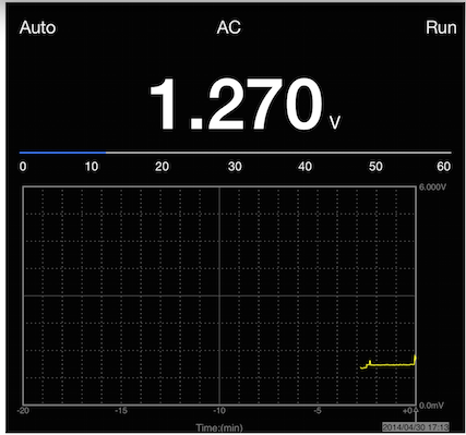
The user can select Auto measure and Manual measure. Voltage range can be set 60.00mV, 600.0mV, 6.000V, 60.00V, 600.0V.
2.2 Making Current Measurement
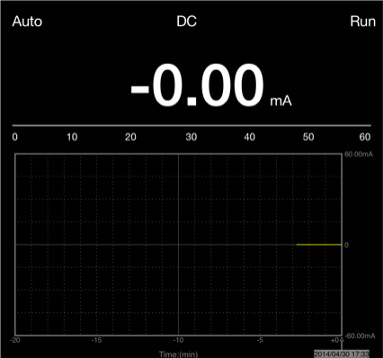
2.2.1 Making a DC Current Measurement
To measure a DC current which is less than 600mA, follow these steps:
- Click the “A” key and then “DC” appears on the screen. The unit on the main reading screen is “mA”. Click “A” key to switch the measurement between mA and A. The default is 600mA. Click “Auto” key to switch the measurement range from 60mA to 600mA.
- Connect the black lead into the COM banana jack input and the red lead into the mA banana jack input.
- Connect the red and black leads to the measured points and the DC current value of measured points will be displayed on the screen.
Connect Data Logger probes(HT325) with Hantek365 as illustrated in the following figure:

Then, the following figure will be displayed on the screen:
To measure a DC current which is larger than 600mA, follow these steps:
- Click the “A” key and then “DC” appears on the screen. The unit on the main reading screen is “mA”, and “mA” will display on the screen, Click “mA” to switch the measurement between mA and 10A. The default is 600mA.
- Click “DC” key and AC will display on the screen.
- Connect the black lead into the COM banana jack input and the red lead into the mA banana jack input.
- Connect the red and black leads to the measured points and the AC current value of measured points will be displayed on the screen.
Connect Data Logger probes(HT325) with Hantek365 as illustrated in the following figure:
Then, the following figure will be displayed on the screen:
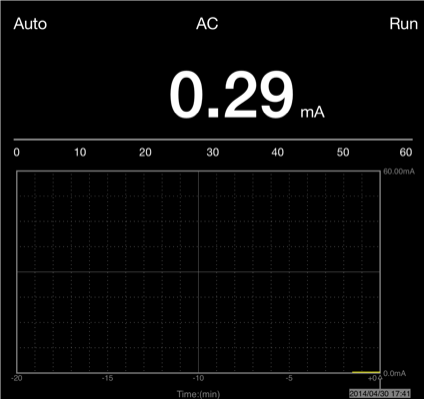
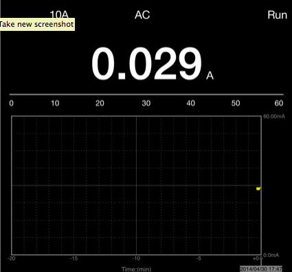
To measure an AC current which is larger than 600mA, follow these steps:
- Click the “A” key and then “DC” appears on the screen. The unit on the main reading screen is mA.
- Click the “DC” key and then “AC” appears on the screen.
- Click “mA” key to switch to10A measurement, the unit on the main reading screen is A.
- Insert the black lead into the COM banana jack input and the red lead into the 10A banana jack input.
- Connect the red and black leads to the measured points and the AC current value of the measure points will be displayed on the screen.
- Click “A” to return to 600mA measurement.
Connect Data Logger probes(HT325) with Hantek365 as illustrated in the following figure:

Then, the following figure will be displayed on the screen:
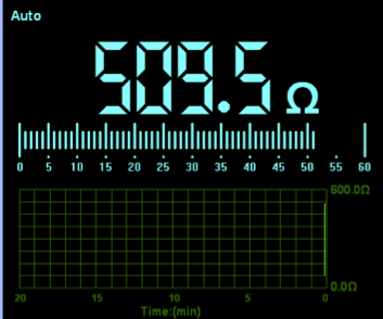
2.3 Measuring Resistance Values
To measure a resistance, follow these steps:
- Click the “OHM” key and then resistance measurement window appears on the screen.
- Connect the black lead into the COM banana jack input and the red lead into the V//C banana jack input.
- Connect the red and black test leads to the resistor. The resistance value is shown on the screen in Ohm.
Connect Data Logger probes(HT325) with Hantek365 as illustrated in the following figure:

Then, the following figure will be displayed on the screen:
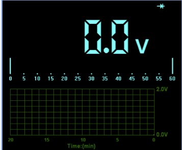
2.4 Making a Diode Measurement
To make a measurement on the diode, follow these steps:
- Click the “Diode” button and a diode symbol appears at the top of the screen.
- Connect the black lead into the COM banana jack input and the red lead into the V/Ω/C banana jack input.
- Connect the red and black leads to the diode and the voltage value of the diode is displayed on the screen in volt.
Connect Data Logger probes(HT325) with Hantek365 as illustrated in the following figure:

Then, the following figure will be displayed on the screen:
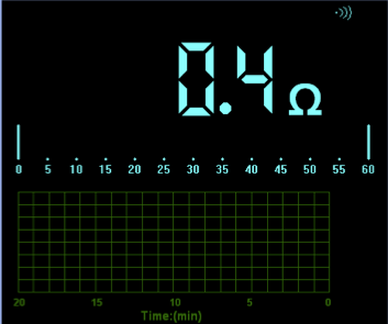
To perform an On-Off test, follow these steps:
- Click the “CONTI” key and then On-Off indictor appears on the top of the screen.
- Connect the black lead into the COM banana jack input and the red lead into the V//C banana jack input.
- Connect the red and black leads to the tested points. If the resistance value of the test points is less than 10 Ω, you will hear beep sound from the test tool.
Connect Data Logger probes(HT325) with Hantek365 as illustrated in the following figure:

Then, the following figure will be displayed on the screen.
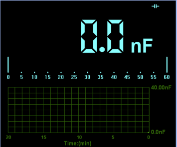
2.5 Making a Capacitance Measurement
To measure a capacitance, follow these steps:
- Click the “CAP” key and a capacitor symbol appears on the top of the screen.
- Connect the black lead into the COM banana jack input and the red lead into the V//C banana jack input.
- Connect the red and black leads to the capacitor and the capacitance value is displayed on the screen in uF or nF.
Connect Data Logger probes(HT325) with Hantek365 as illustrated in the following figure:

Then, the following figure will be displayed on the screen.
2.6 Selecting Automatic/Manual Range Adjustment
The default range mode of the instrument is automatic range. If you are using the DC/AC mode, to switch to the manual range, do these steps:
- Click “Auto” key to enter the manual range mode and then Manual is displayed on the top of the screen.
- Under the manual range mode, the measuring range is increased by a stage, Click “Auto” to switch manual.
- Click “Manual” key to switch back to the automatic range mode and then Auto is displayed on the top of the screen.
Attention: capacitance measurement without manual range mode.
2.7 Taking a Relative Measurement
A currently measured result relative to the defined reference value is displayed in a relative measurement.
The following example shows how to take a relative measurement. At first, it is required to acquire a reference value.
- Click the V/A/OHM/CAP key.
- Connect the black lead into the COM banana jack input and the red lead into the V///C banana jack input.
- Connect the red and black test leads to the tested device. The value is shown on the screen.
- Click
 button then
  is displayed on the top right of the screen. The saved reference value is displayed beside.
Then, the following figure will be displayed on the screen.
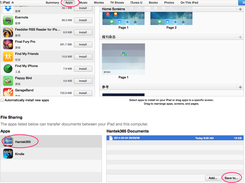
2.8 How to get saved logging file?
- Connect the iPad and Computer via USB
- Open the iTunes on the Computer, click the iPad button

- Click the "Apps" button
 .
.
- In the bootom "File Sharing" Section, click the Hantek365, then click one of the file in the "Hantek365 Cocuments" list, then you can get the saved file through the "Saved to" button.
Chapter 3: Appendix
Specification:
| Maximum Resolution |
6000 Counts |
| DMM Testing Modes |
Voltage, Current, Resistance, Capacitance, Diode & Continuity |
| Maximum Input Voltage |
AC: 600V DC: 800V |
| Maximum Input Current |
AC: 10A DC: 10A |
| Input Impedance |
10MΩ |
Meter Specification:
| Range |
Accuracy |
Resolution |
| DC Voltage |
60.00mV |
±1%±1 digit |
10uV |
| 600.00mV |
100uV |
| 6.00V |
1mV |
| 60.00V |
10mV |
| 600.0V |
100mV |
| 800V |
1V |
| AC Volatage |
60.00mV |
±1%±3 digit |
10uV |
| 600.0mV |
100uV |
| 6.000V |
1mV |
| 60.00V |
10mV |
| 600.0V |
100mV |
| DC Current |
60.00mA |
±1.5%±1 digit |
10uA |
| 600.0mA |
±1%±1 digit |
100uA |
| 6.000A |
±1.5%±3digit |
mA |
| 10.00A |
10mA |
| AC Current |
60.00mA |
±1.5%±1 digit |
10uA |
| 600.0mA |
±1%±1 digit |
100uA |
| 6.000A |
±1.5%±3digit |
mA |
| 10.00A |
10mA |
| Resistance |
600.0 |
±1%±3digit |
0.1Ω |
| 6.000K |
±1%±1digit |
1Ω |
| 60.00K |
10Ω |
| 600.00K |
100Ω |
| 6.000M |
1KΩ |
| 60.00M |
±1.5%±3digit |
10KΩ |
| Capacitance |
40.00nF |
±1%±1digit |
10pF |
| 400.0nF |
100pF |
| 4.000uF |
1nF |
| 40.00uF |
10nF |
| 400.0uF |
100nF |
| Diode |
0V~2.0V |
| On-Off Test |
<10Ω |
Difference:
| Type |
Bluetooth |
Lithium battery |
RMS |
| Hantek365E |
YES |
YES |
- |
| Hantek365F |
YES |
YES |
YES |