


| Model | HDM3065H | HDM3065B | HDM3065A | HDM3065S | HDM3065 |
| Resolution bit | 6 1/2 | 6 1/2 | 6 1/2 | 6 1/2 | 6 1/2 |
| DCV basic precision | 35 ppm | 35 ppm | 35 ppm | 35 ppm | 35 ppm |
| Maximum reading rate | 30,000 rdgs/s | 30,000 rdgs/s | 30,000 rdgs/s | 30,000 rdgs/s | 30,000 rdgs/s |
| Memory | 10,000 readings | 10,000 readings | 10,000 readings | 10,000 readings | 10,000 readings |
| Double-display measurement function | √ | √ | √ | √ | √ |
| Statistical graph |
Histogram,
bar graph, trend graph |
Histogram,
bar graph, trend graph |
Histogram,
bar graph, trend graph |
Histogram,
bar graph, trend graph |
Histogram,
bar graph, trend graph |
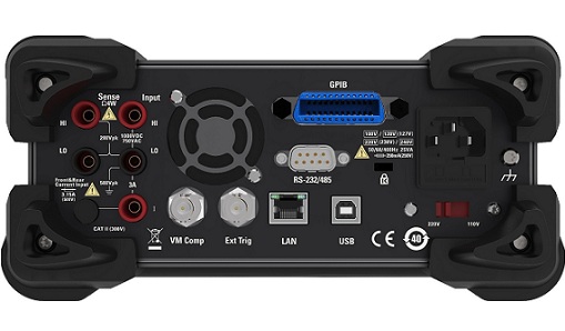
| Interface | USB、232/485、LAN、GPIB | USB、232/485、LAN | USB、232/485 | USB、232/485 | USB、232/485 |
| Input terminal |
Front-panel Rear-panel |
Front-panel Rear-panel |
Front-panel Rear-panel |
Rear-panel | Front-panel |
| Range2 /frequency | 24 hours3 | 90 days | 1 year | 2 years | temperature coefficient/℃ 4 | |
| DC Voltage | TCAL±1℃ | TCAL±5℃ | TCAL±5℃ | TCAL±5℃ | ||
| 100 mV | 0.0030+0.0030 | 0.0040+0.0035 | 0.0050+0.0035 | 0.0065+0.0035 | 0.0005+0.0005 | |
| 1 V | 0.0020+0.0006 | 0.0030+0.0007 | 0.0040+0.0007 | 0.0055+0.0007 | 0.0005+0.0001 | |
| 10 V | 0.0015+0.0004 | 0.0020+0.0005 | 0.0035+0.0005 | 0.0050+0.0005 | 0.0005+0.0001 | |
| 100 V | 0.0020+0.0006 | 0.0035+0.0006 | 0.0045+0.0006 | 0.0060+0.0006 | 0.0005+0.0001 | |
| 1000 V | 0.0020+0.0006 | 0.0035+0.0010 | 0.0045+0.0010 | 0.0060+0.0010 | 0.0005+0.0001 | |
| True RMS AC voltage2,5,6 | ||||||
| 100 mV、1 V、10 V、100 V and 750 V range | ||||||
| 5 Hz - 10 Hz | 0.35+0.02 | 0.35+0.03 | 0.35+0.03 | 0.35+0.03 | 0.035+0.003 | |
| 10 Hz-20 KHz | 0.04+0.02 | 0.05+0.03 | 0.06+0.03 | 0.07+0.03 | 0.005+0.003 | |
| 20 KHz-50 KHz | 0.10+0.04 | 0.11+0.05 | 0.12+0.05 | 0.13+0.05 | 0.011+0.005 | |
| 50 KHz-100 KHz | 0.55+0.08 | 0.60+0.08 | 0.60+0.08 | 0.60+0.08 | 0.060+0.008 | |
| 100 KHz-300 KHz | 4.00+0.50 | 4.00+0.50 | 4.00+0.50 | 4.00+0.50 | 0.200+0.020 | |
| Resistance7 | Testing current | |||||
| 100 Ω | 1 mA | 0.0030+0.0030 | 0.008+0.004 | 0.010+0.004 | 0.012+0.004 | 0.0006+0.0005 |
| 1 kΩ | 1 mA | 0.0020+0.0005 | 0.008+0.001 | 0.010?0.001 | 0.012+0.001 | 0.0006+0.0001 |
| 10 kΩ | 100 μA | 0.0020+0.0005 | 0.008+0.001 | 0.010+0.001 | 0.012+0.001 | 0.0006+0.0001 |
| 100 kΩ | 10 μA | 0.0020+0.0005 | 0.008+0.001 | 0.010+0.001 | 0.012+0.001 | 0.0006+0.0001 |
| 1 MΩ | 5 μA | 0.002+0.001 | 0.008+0.001 | 0.010+0.001 | 0.012+0.001 | 0.0010+0.0002 |
| 10 MΩ | 500 nA | 0.015+0.001 | 0.020+0.001 | 0.040+0.001 | 0.060+0.001 | 0.0030+0.0004 |
| 100 MΩ | 500 nA‖10 MΩ | 0.300+0.010 | 0.800+0.010 | 0.800+0.010 | 0.800+0.010 | 0.1500+0.0002 |
| DCcurrent | Potential drop of internal resistance | |||||
| 100 μA | <0.11V | 0.010+0.020 | 0.040+0.025 | 0.050+0.025 | 0.060+0.025 | 0.0020+0.0030 |
| 1 mA | <0.11V | 0.007+0.006 | 0.030+0.006 | 0.050+0.006 | 0.060?0.006 | 0.0020+0.0005 |
| 10 mA | <0.05V | 0.007+0.020 | 0.030+0.020 | 0.050+0.020 | 0.060+0.020 | 0.0020+0.0020 |
| 100 mA | <0.5V | 0.010+0.004 | 0.030+0.005 | 0.050+0.005 | 0.060+0.005 | 0.0020+0.0005 |
| 1 A | <0.7V | 0.050+0.006 | 0.080+0.010 | 0.100+0.010 | 0.120+0.010 | 0.0050+0.0010 |
| 3 A | <2.0V | 0.180+0.020 | 0.200+0.020 | 0.200+0.020 | 0.230+0.020 | 0.0050+0.0020 |
| 10 A8 | <0.5V | 0.050+0.010 | 0.120+0.010 | 0.120+0.010 | 0.150+0.010 | 0.0050+0.0010 |
| Capacitance15 | ||||||
| 1.0000 nF | 0.50+0.50 | 0.50+0.50 | 0.50+0.50 | 0.50+0.50 | 0.05+0.05 | |
| 10.000 nF | 0.40+0.10 | 0.40+0.10 | 0.40+0.10 | 0.40+0.10 | 0.05+0.01 | |
| 100.00 nF | 0.40+0.10 | 0.40+0.10 | 0.40+0.10 | 0.40+0.10 | 0.05+0.01 | |
| 1.0000 μF | 0.40+0.10 | 0.40+0.10 | 0.40+0.10 | 0.40+0.10 | 0.05+0.01 | |
| 10.000 μF | 0.40+0.10 | 0.40+0.10 | 0.40+0.10 | 0.40+0.10 | 0.05+0.01 | |
| 100.00 μF | 0.40+0.10 | 0.40+0.10 | 0.40+0.10 | 0.40+0.10 | 0.05+0.01 | |
| Range2/frequency | 24hours3 | 90days | 1year | 2years | temperature coefficient/℃4 | |
| TCAL ± 1℃ | TCAL ± 5℃ | TCAL ± 5℃ | TCAL ± 5℃ | |||
| True RMS AC current2,6,9 | Potentia drop of internal resistance | |||||
| 100 μA、1 mA、10 mA and 100 mA range | <0.011,<0.11, <0.05,<0.5V | |||||
| 3 Hz - 5 kHz | 0.10+0.04 | 0.10+0.04 | 0.10+0.04 | 0.10+0.04 | 0.015+0.006 | |
| 5-10kHz | 0.10+0.04 | 0.10+0.04 | 0.10+0.04 | 0.10+0.04 | 0.030+0.006 | |
| (typicalvalue) | ||||||
| 1Arange | <0.7V | |||||
| 3Hz-5kHz | 0.10+0.04 | 0.10+0.04 | 0.10+0.04 | 0.10+0.04 | 0.015+0.006 | |
| 5 kHz - 10 kHz(Typicalvalue) | 0.10+0.04 | 0.10+0.04 | 0.10+0.04 | 0.10+0.04 | 0.030+0.006 | |
| 3 A Range | <2.0V | |||||
| 3 Hz - 5 kHz | 0.23+0.04 | 0.23+0.04 | 0.23+0.04 | 0.23+0.04 | 0.015+0.006 | |
| 5 kHz - 10 kHz | 0.23+0.04 | 0.23+0.04 | 0.23+0.04 | 0.23+0.04 | 0.030+0.006 | |
| (Typicalvalue) | ||||||
| 10 A Range8 | <0.5V | |||||
| 3 Hz - 5 kHz | 0.15+0.04 | 0.15+0.04 | 0.15+0.04 | 0.15+0.04 | 0.015+0.006 | |
| 5 kHz -10 kHz(Typicalvalue) | 0.15+0.04 | 0.15+0.04 | 0.15+0.04 | 0.15+0.04 | 0.030+0.006 | |
| Connectivity | ||||||
| 1 kΩ | 0.002+0.030 | 0.008+0.030 | 0.010+0.030 | 0.012+0.030 | 0.0010+0.0020 | |
| DiodeTesting10 | ||||||
| 5 V | 0.002+0.030 | 0.008+0.030 | 0.010+0.030 | 0.012+0.030 | 0.0010+0.0020 | |
| DCrate(Typicalvalue) | ||||||
| (Normalize precision input)+(Normalize reference accuracy) | ||||||
| Temperature11 | ||||||
| PT100 (DIN/IEC751) | Theprobe accuracy+0.05℃ | |||||
| 5 kΩ thermistor | Theprobe accuracy+0.1℃ | |||||
| Frequency:Technical Indicator±(%reading)12.13 | ||||||
| 100mV、1V、10、100V and 750 V range 14 | ||||||
| 3 Hz-10 Hz | 0.1 | 0.1 | 0.1 | 0.1 | 0.1 | |
| 10 Hz-100 Hz | 0.03 | 0.03 | 0.03 | 0.03 | 0.035 | |
| 100 Hz-1 KHz | 0 | 0.008 | 0.01 | 0.01 | 0.015 | |
| 1 KHz-300 KHz | 0.002 | 0.006 | 0.01 | 0.01 | 0.015 | |
| Square wave15 | 0.001 | 0.006 | 0.01 | 0.01 | 0.015 | |
| Extra Gate timeerror ± (%reading)13 | ||||||
| Frequency | 1second | 0.1second | 0.01second | |||
| 3 Hz-40 Hz | 0 | 0.2 | 0.2 | |||
| 40 Hz-100 Hz | 0 | 0.06 | 0.2 | |||
| 100 Hz-1 KHz | 0 | 0.02 | 0.2 | |||
| 1 KHz-300 KHz | 0 | 0.004 | 0.03 | |||
| Square wave15 | 0 | 0 | 0 | |||
| Range2 /frequency | 24 hours3 | 90 days | 1 year | 2 years | temperature coefficient/℃ 4 | |
| DC Voltage | TCAL±1℃ | TCAL±5℃ | TCAL±5℃ | TCAL±5℃ | ||
| 100 mV | 0.0030+0.0030 | 0.0040+0.0035 | 0.0050+0.0035 | 0.0065+0.0035 | 0.0005+0.0005 | |
| 1 V | 0.0020+0.0006 | 0.0030+0.0007 | 0.0040+0.0007 | 0.0055+0.0007 | 0.0005+0.0001 | |
| 10 V | 0.0015+0.0004 | 0.0020+0.0005 | 0.0035+0.0005 | 0.0050+0.0005 | 0.0005+0.0001 | |
| 100 V | 0.0020+0.0006 | 0.0035+0.0006 | 0.0045+0.0006 | 0.0060+0.0006 | 0.0005+0.0001 | |
| 1000 V | 0.0020+0.0006 | 0.0035+0.0010 | 0.0045+0.0010 | 0.0060+0.0010 | 0.0005+0.0001 | |
| True RMS AC voltage2,5,6 | ||||||
| 100 mV、1 V、10 V、100 V and 750 V range | ||||||
| 5 Hz - 10 Hz | 0.35+0.02 | 0.35+0.03 | 0.35+0.03 | 0.35+0.03 | 0.035+0.003 | |
| 10 Hz-20 KHz | 0.04+0.02 | 0.05+0.03 | 0.06+0.03 | 0.07+0.03 | 0.005+0.003 | |
| 20 KHz-50 KHz | 0.10+0.04 | 0.11+0.05 | 0.12+0.05 | 0.13+0.05 | 0.011+0.005 | |
| 50 KHz-100 KHz | 0.55+0.08 | 0.60+0.08 | 0.60+0.08 | 0.60+0.08 | 0.060+0.008 | |
| 100 KHz-300 KHz | 4.00+0.50 | 4.00+0.50 | 4.00+0.50 | 4.00+0.50 | 0.200+0.020 | |
| Resistance7 | Testing current | |||||
| 100 Ω | 1 mA | 0.0030+0.0030 | 0.008+0.004 | 0.010+0.004 | 0.012+0.004 | 0.0006+0.0005 |
| 1 kΩ | 1 mA | 0.0020+0.0005 | 0.008+0.001 | 0.010?0.001 | 0.012+0.001 | 0.0006+0.0001 |
| 10 kΩ | 100 μA | 0.0020+0.0005 | 0.008+0.001 | 0.010+0.001 | 0.012+0.001 | 0.0006+0.0001 |
| 100 kΩ | 10 μA | 0.0020+0.0005 | 0.008+0.001 | 0.010+0.001 | 0.012+0.001 | 0.0006+0.0001 |
| 1 MΩ | 5 μA | 0.002+0.001 | 0.008+0.001 | 0.010+0.001 | 0.012+0.001 | 0.0010+0.0002 |
| 10 MΩ | 500 nA | 0.015+0.001 | 0.020+0.001 | 0.040+0.001 | 0.060+0.001 | 0.0030+0.0004 |
| 100 MΩ | 500 nA‖10 MΩ | 0.300+0.010 | 0.800+0.010 | 0.800+0.010 | 0.800+0.010 | 0.1500+0.0002 |
| DCcurrent | Potential drop of internal resistance | |||||
| 100 μA | <0.11V | 0.010+0.020 | 0.040+0.025 | 0.050+0.025 | 0.060+0.025 | 0.0020+0.0030 |
| 1 mA | <0.11V | 0.007+0.006 | 0.030+0.006 | 0.050+0.006 | 0.060?0.006 | 0.0020+0.0005 |
| 10 mA | <0.05V | 0.007+0.020 | 0.030+0.020 | 0.050+0.020 | 0.060+0.020 | 0.0020+0.0020 |
| 100 mA | <0.5V | 0.010+0.004 | 0.030+0.005 | 0.050+0.005 | 0.060+0.005 | 0.0020+0.0005 |
| 1 A | <0.7V | 0.050+0.006 | 0.080+0.010 | 0.100+0.010 | 0.120+0.010 | 0.0050+0.0010 |
| 3 A | <2.0V | 0.180+0.020 | 0.200+0.020 | 0.200+0.020 | 0.230+0.020 | 0.0050+0.0020 |
| 10 A8 | <0.5V | 0.050+0.010 | 0.120+0.010 | 0.120+0.010 | 0.150+0.010 | 0.0050+0.0010 |
| Capacitance15 | ||||||
| 1.0000 nF | 0.50+0.50 | 0.50+0.50 | 0.50+0.50 | 0.50+0.50 | 0.05+0.05 | |
| 10.000 nF | 0.40+0.10 | 0.40+0.10 | 0.40+0.10 | 0.40+0.10 | 0.05+0.01 | |
| 100.00 nF | 0.40+0.10 | 0.40+0.10 | 0.40+0.10 | 0.40+0.10 | 0.05+0.01 | |
| 1.0000 μF | 0.40+0.10 | 0.40+0.10 | 0.40+0.10 | 0.40+0.10 | 0.05+0.01 | |
| 10.000 μF | 0.40+0.10 | 0.40+0.10 | 0.40+0.10 | 0.40+0.10 | 0.05+0.01 | |
| 100.00 μF | 0.40+0.10 | 0.40+0.10 | 0.40+0.10 | 0.40+0.10 | 0.05+0.01 | |
| Range2/frequency | 24hours3 | 90days | 1year | 2years | temperature coefficient/℃4 | |
| TCAL ± 1℃ | TCAL ± 5℃ | TCAL ± 5℃ | TCAL ± 5℃ | |||
| True RMS AC current2,6,9 | Potentia drop of internal resistance | |||||
| 100 μA、1 mA、10 mA and 100 mA range | <0.011,<0.11, <0.05,<0.5V | |||||
| 3 Hz - 5 kHz | 0.10+0.04 | 0.10+0.04 | 0.10+0.04 | 0.10+0.04 | 0.015+0.006 | |
| 5-10kHz | 0.10+0.04 | 0.10+0.04 | 0.10+0.04 | 0.10+0.04 | 0.030+0.006 | |
| (typicalvalue) | ||||||
| 1Arange | <0.7V | |||||
| 3Hz-5kHz | 0.10+0.04 | 0.10+0.04 | 0.10+0.04 | 0.10+0.04 | 0.015+0.006 | |
| 5 kHz - 10 kHz(Typicalvalue) | 0.10+0.04 | 0.10+0.04 | 0.10+0.04 | 0.10+0.04 | 0.030+0.006 | |
| 3 A Range | <2.0V | |||||
| 3 Hz - 5 kHz | 0.23+0.04 | 0.23+0.04 | 0.23+0.04 | 0.23+0.04 | 0.015+0.006 | |
| 5 kHz - 10 kHz | 0.23+0.04 | 0.23+0.04 | 0.23+0.04 | 0.23+0.04 | 0.030+0.006 | |
| (Typicalvalue) | ||||||
| 10 A Range8 | <0.5V | |||||
| 3 Hz - 5 kHz | 0.15+0.04 | 0.15+0.04 | 0.15+0.04 | 0.15+0.04 | 0.015+0.006 | |
| 5 kHz -10 kHz(Typicalvalue) | 0.15+0.04 | 0.15+0.04 | 0.15+0.04 | 0.15+0.04 | 0.030+0.006 | |
| Connectivity | ||||||
| 1 kΩ | 0.002+0.030 | 0.008+0.030 | 0.010+0.030 | 0.012+0.030 | 0.0010+0.0020 | |
| DiodeTesting10 | ||||||
| 5 V | 0.002+0.030 | 0.008+0.030 | 0.010+0.030 | 0.012+0.030 | 0.0010+0.0020 | |
| DCrate(Typicalvalue) | ||||||
| (Normalize precision input)+(Normalize reference accuracy) | ||||||
| Temperature11 | ||||||
| PT100 (DIN/IEC751) | Theprobe accuracy+0.05℃ | |||||
| 5 kΩ thermistor | Theprobe accuracy+0.1℃ | |||||
| Frequency:Technical Indicator±(%reading)12.13 | ||||||
| 100mV、1V、10、100V and 750 V range 14 | ||||||
| 3 Hz-10 Hz | 0.1 | 0.1 | 0.1 | 0.1 | 0.1 | |
| 10 Hz-100 Hz | 0.03 | 0.03 | 0.03 | 0.03 | 0.035 | |
| 100 Hz-1 KHz | 0.003 | 0.008 | 0.01 | 0.01 | 0.015 | |
| 1 KHz-300 KHz | 0.002 | 0.006 | 0.01 | 0.01 | 0.015 | |
| Square wave15 | 0.001 | 0.006 | 0.01 | 0.01 | 0.015 | |
| Extra Gate timeerror ± (%reading)13 | ||||||
| Frequency | 1second | 0.1second | 0.01second | |||
| 3 Hz-40 Hz | 0 | 0.2 | 0.2 | |||
| 40 Hz-100 Hz | 0 | 0.06 | 0.2 | |||
| 100 Hz-1 KHz | 0 | 0.02 | 0.2 | |||
| 1 KHz-300 KHz | 0 | 0.004 | 0.03 | |||
| Square wave15 | 0 | 0 | 0 | |||