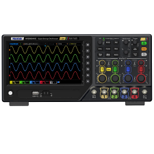
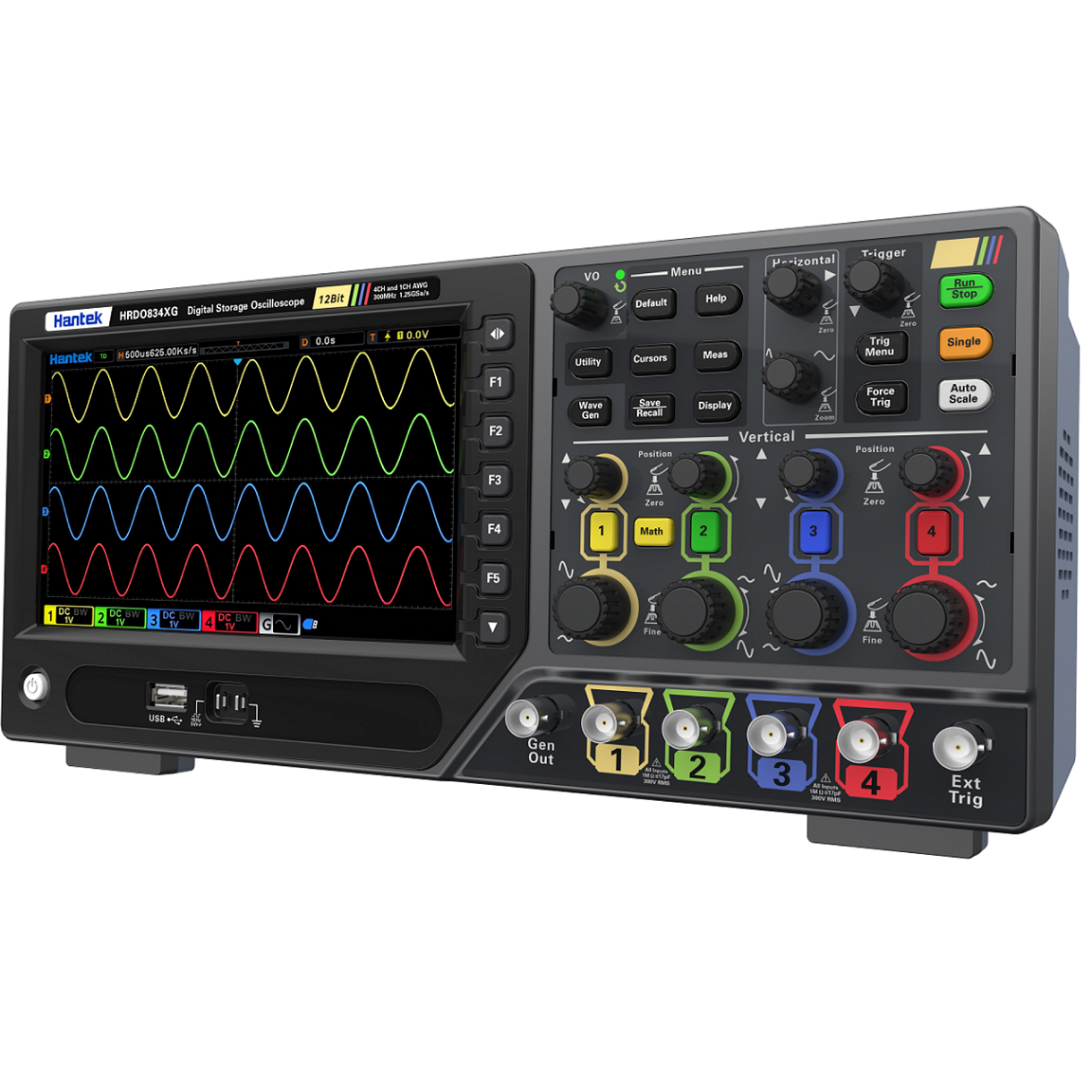
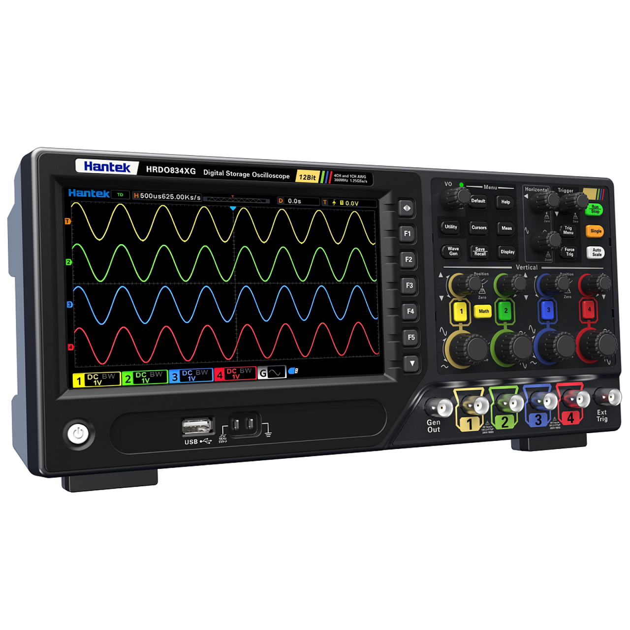
HRDO800 series
| Model | Channel | Sampling Rate | Bandwidth | Signal Source |
| HRDO802X | 2 | 1.25GSa/s | 80MHz | - |
| HRDO804X | 4 | 1.25GSa/s | 80MHz | - |
| HRDO812X | 2 | 1.25GSa/s | 120MHz | - |
| HRDO814X | 4 | 1.25GSa/s | 120MHz | - |
| HRDO822X | 2 | 1.25GSa/s | 250MHz | - |
| HRDO824X | 4 | 1.25GSa/s | 250MHz | - |
| HRDO832X | 2 | 1.25GSa/s | 300MHz | - |
| HRDO834X | 4 | 1.25GSa/s | 300MHz | - |
| HRDO802XG | 2 | 1.25GSa/s | 80MHz | 1 |
| HRDO804XG | 4 | 1.25GSa/s | 80MHz | 1 |
| HRDO812XG | 2 | 1.25GSa/s | 120MHz | 1 |
| HRDO814XG | 4 | 1.25GSa/s | 120MHz | 1 |
| HRDO822XG | 2 | 1.25GSa/s | 250MHz | 1 |
| HRDO824XG | 4 | 1.25GSa/s | 250MHz | 1 |
| HRDO832XG | 2 | 1.25GSa/s | 300MHz | 1 |
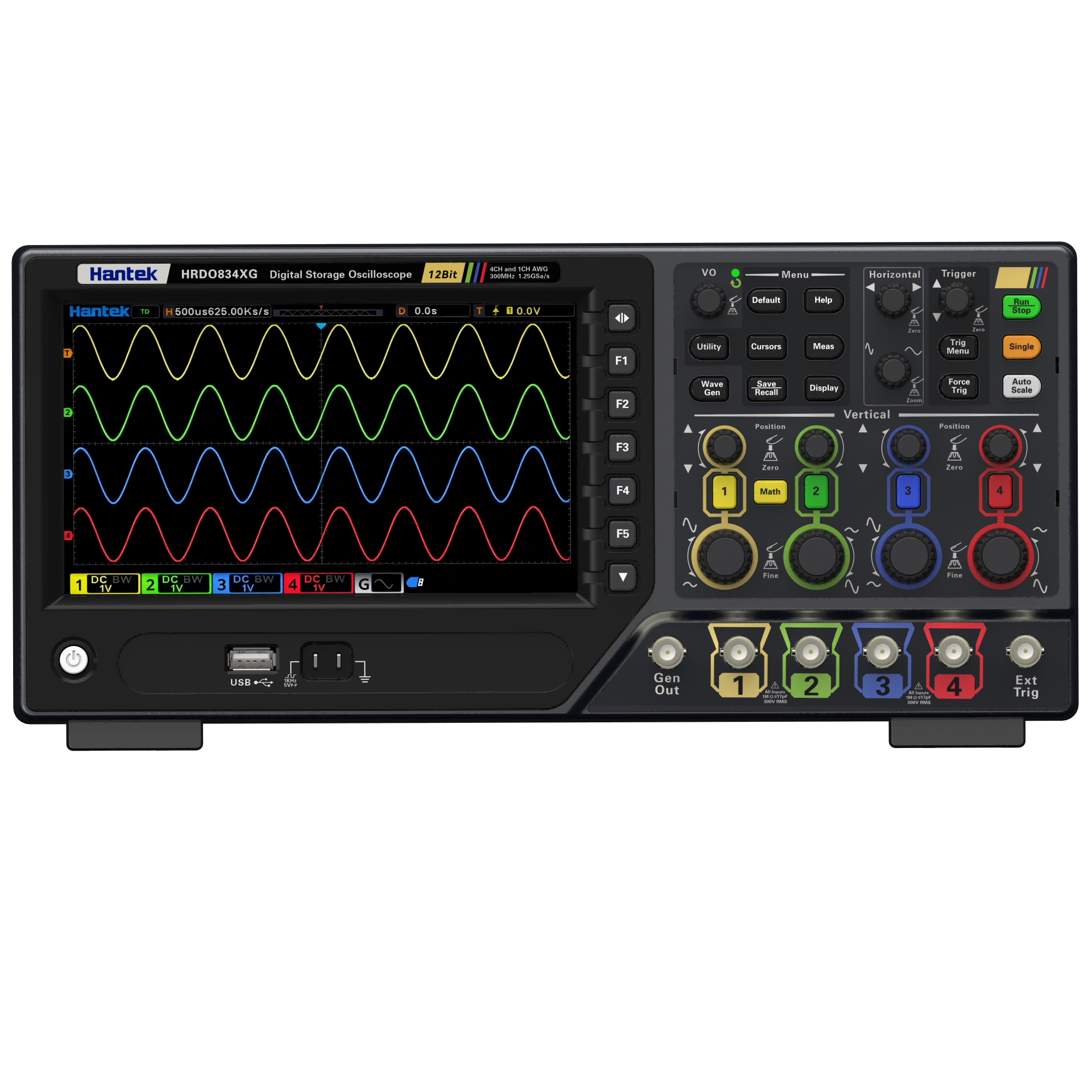
| HRDO834XG | 4 | 1.25GSa/s | 300MHz | 1 |
| Specifications | ||
| No. of Input Channels |
2 analog channel input/4 analog channel input 1 EXT channel input 1 GEN OUT channel(HRDO800XG series) |
|
| Sampling Mode | Real-time sampling | |
| Max. Sample Rate of Analog Channel |
1.25GSa/s(single-channel) 625MSa/s(dual-channel) 312.5MSa/s(all channels) |
|
| Max. Memory Depth |
125Mpts(single-channel), 50Mpts(dual-channel) 25Mpts(all-channel) |
|
| Peak Detection | Under all the time base settings, capture 1ns glitches | |
| LCD Size and Type | 7-inch display screen | |
| Display Resolution | 1024*600 | |
| Vertical System Analog Channel | ||
| Input Coupling | DC, AC, GND | |
| InputImpedance | 1MΩ ± 1% | |
| Input Capacitance | 17pF±3pF | |
| Maximum Input Voltage | CATⅡ300 VRMS, 400Vpk; Transient overvoltage 1600 Vpk | |
| Vertical Resolution | 12bit | |
| Vertical Sensitivity Range | 500uV/div ~ 10V/div | |
| Offset Range | 500μV/div~20mV/div, ±400mV | |
| 50mV/div~200mV/div, ±2V | ||
| 500mV/div~2V/div, ±40V | ||
| 5V/div~10V/div, ±50V | ||
| Dynamic Range | ±5div (12bit) | |
| Bandwidth Limit | 20MHz; selectable for each channel | |
| DC Gain Accuracy | ± 3% FullScale | |
| DC Offset Accuracy | <200mV/div (±0.1 div±2 mV±1.5%of offset value) | |
| >200mV/div (±0.1 div±2 mV±1.0%of offset value) | ||
| Channel-to-Channel Isolation | 40dB, from DC to maximum rated bandwidth of each model | |
| ESD | ±4kV | |
| Horizontal System--Analog Channel | ||
| Range of Time Base | 500ps/div-1ks/div | |
| Time Base Accuracy | ±50ppm±1ppm/year | |
|
Time Base Delay Range |
before triggering: 8 × SEC/DIV | |
| after triggering: 10 × SEC/DIV | ||
| Time Interval (△T) | Measurement±(1 sample interval)±(2ppm×readout)±50ps | |
| Horizontal Mode | YT:Default | |
| XY:X1=CH1,Y1=CH2,X2=CH3,Y2=CH4 | ||
| SCAN:Time base≥100ms/div,available to enter or exit the SCAN mode by rotating the Horizontal SCALE. | ||
| ROLL:Time base≥100ms/div,available to enter or exit ROLL mode by accessing the menu. | ||
| Acquisition System | ||
| Max. Sample Rate of Analog Channel |
1.25GSa/s(single-channel) 625MSa/s(dual-channel) 312.5MSa/s(all channels) |
|
| Max. Memory Depth |
125Mpts(single-channel), 50Mpts(dual-channel) 25Mpts(all-channel) |
|
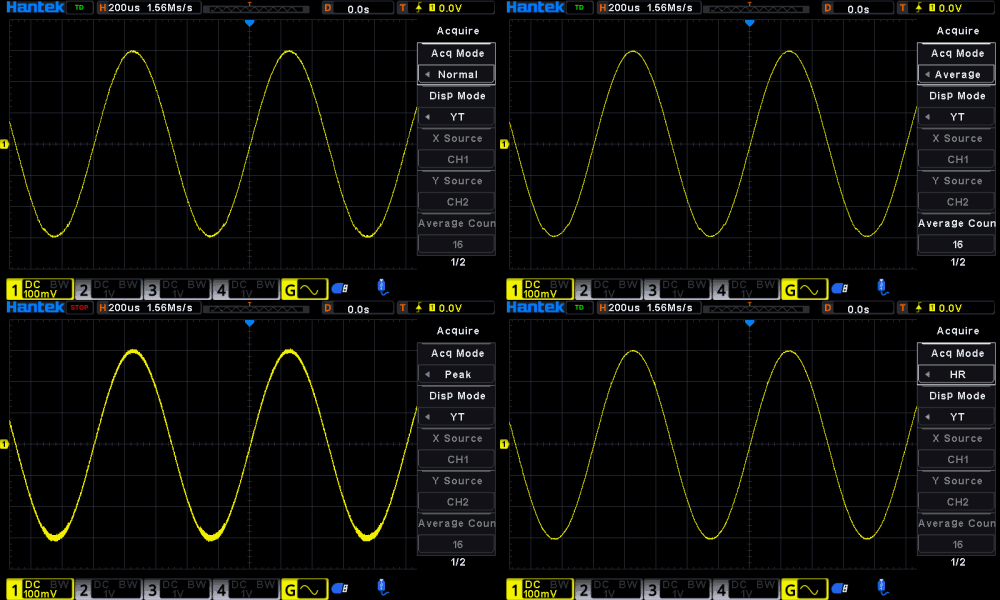
| Acquisition Mode | Normal | Default |
| Peak Detection | Capture 1ns glitches | |
| Average Mode | 2, 4, 8, 16…128 are available for you to choose, averaging point by point | |
| High Resolution | 16 bits (max.) | |
| Trigger System | ||
| Trigger Source | Analog channel(CH1-CH4), EXT | |
| Trigger Mode | Auto, Normal, Single | |
| Holdoff Range | 8ns-10s | |
| Trigger Sensitivity | CH1-CH4 | 1 div or 5 mVpp, whichever is larger, <10mV/div |
| 0.5 div, ≥10mV/div | ||
| Trigger Level Range | CH1-CH4 | ± 4 div from the center of the screen |
| EXT | -1.3V-6.5V | |
| Trigger Type | ||
| Trigger Type |
Edge trigger, Pulse trigger, Slope trigger, Overtime trigger, Window trigger, Internal trigger, Under Amp trigger, UART trigger, LIN trigger, CAN trigger, SPI trigger, IIC trigger |
|
| Edge trigger |
Identify triggers by searching for specified edges (rising edge, falling edge, double edge) and voltage levels on the waveform. |
|
| Source channel: CH1~CH4, EXT. | ||
| Pulse trigger |
Set the oscilloscope to trigger on positive or negative pulses of a specified width. You can set the trigger source, polarity (positive, negative), trigger conditions, and pulse width in this menu. |
|
| Source channel: CH1~CH4. | ||
| Slope trigger | Set the oscilloscope to trigger a positive or negative slope from one level to another within a specified time. | |
| Source channel: CH1~CH4. | ||
| Overtime trigger |
Triggered when the time interval (△ T) from the rising edge (or falling edge) of the input signal through the trigger level to the adjacent falling edge (or rising edge) through the trigger level is greater than the set timeout. |
|
| Source channel: CH1~CH4. | ||
| Window trigger |
Window triggering provides high and low triggering levels. When the input signal passes through a high or low trigger level, the oscilloscope triggers. |
|
| Source channel: CH1~CH4. | ||
| Internal trigger |
Triggered when the interval between two consecutive rising (or falling) edges satisfies the set time condition (<,>,!=,=). |
|
| Source channel: CH1~CH4. | ||
| Under Amp trigger | Used to trigger a pulse that crosses one trigger level but does not cross another trigger level. | |
| Source channel: CH1~CH4. | ||
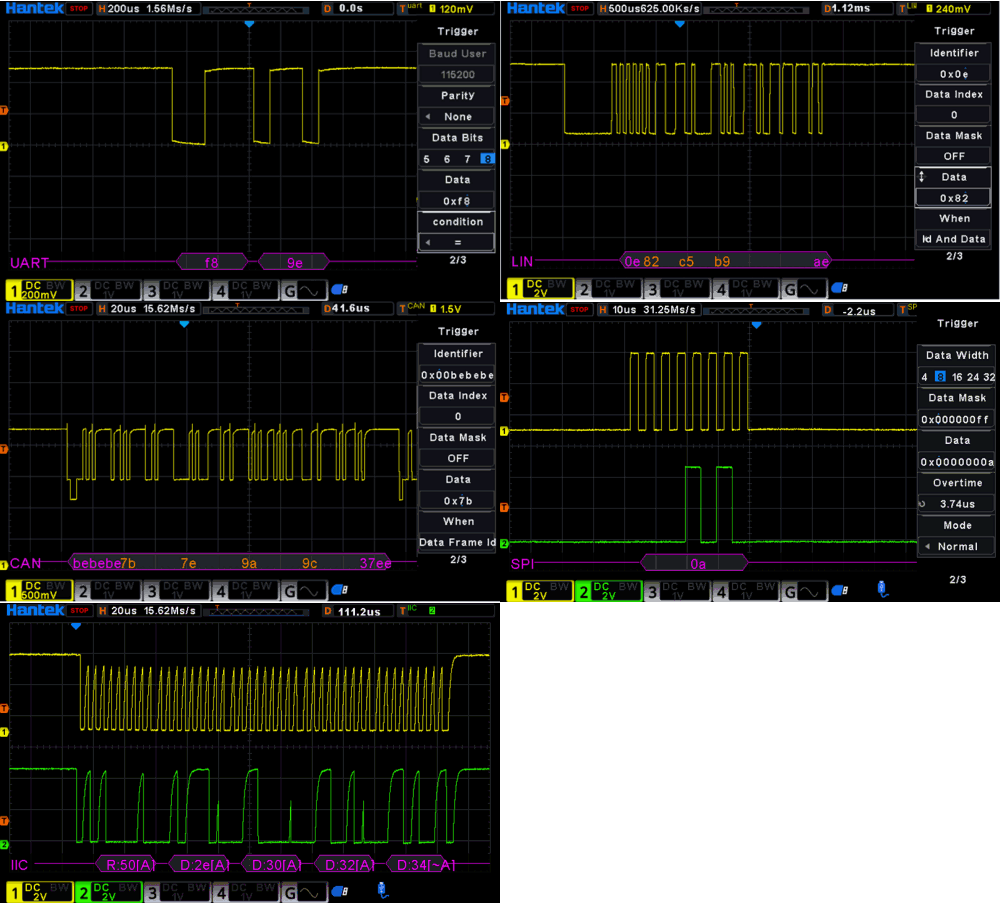
| UART trigger |
Triggering of frame start, frame end, data, checksum errors, and acceptance errors when UART signals are detected. |
|
| Source channel: CH1~CH4. | ||
| LIN trigger | Triggered on the synchronization field of LIN signal, or on specified identifiers, data, or frames. | |
| Source channel: CH1~CH4. | ||
| CAN trigger |
Triggered at the beginning of a CAN signal frame, on a specified type of frame (such as remote frame, data frame, etc.), or on a specified type of error frame. |
|
| Source channel: CH1~CH4. | ||
| SPI trigger | When the timeout condition is met, the oscilloscope triggers when it searches for the specified data. | |
| Source channel: CH1~CH4. | ||
| I2C trigger | Triggered on the start bit, stop bit, no response, address, restart, address, and data of the I2C bus. | |
| Source channel: CH1~CH4. | ||
| Waveform Measurement | ||
| Cursor | Number of Cursors | 2 pairs of XY cursors |
| Manual Mode | Voltage deviation between cursors | |
| Time deviation between cursors | ||
| Reciprocal of dX (1/dX) | ||
| Track Mode | Fix Y-axis to track X-axis waveform point's voltage and time values | |
| Fix X-axis to track Y-axis waveform point's voltage and time values | ||
| XY Mode | Measure the voltage parameters of the corresponding channel waveforms in XY time base mode. | |
| X1=CH1,Y1=CH2,X2=CH3,Y2=CH4 | ||
| Auto Measurement | Number of Measurements | Up to 4 measurements can be displayed at a time. |
| Measurement Source | CH1-CH4 | |
| All Measurement |
Display 32 measurement items for the current measurement channel, with continuously updated measurement results and switchable measurement channels. |
|
| Type |
PKPK, Freq, Average, Vmax, Vmin, Period, Vtop, Vmid, Vbase, Vamp, RMS, OverShoot, PreShoot, PrdRms, PrdAvg, RiseTime, FallTime, +Width, -Width, +Duty, -Duty, FRR, FFF, FOV, FPRE, BWidth, FRF, FFR, LRR, LRF, LFR, LFF |
|
| Statistics | Cur, Avg, Max, Min, Rmse, Count | |
| Waveform Calculation | ||
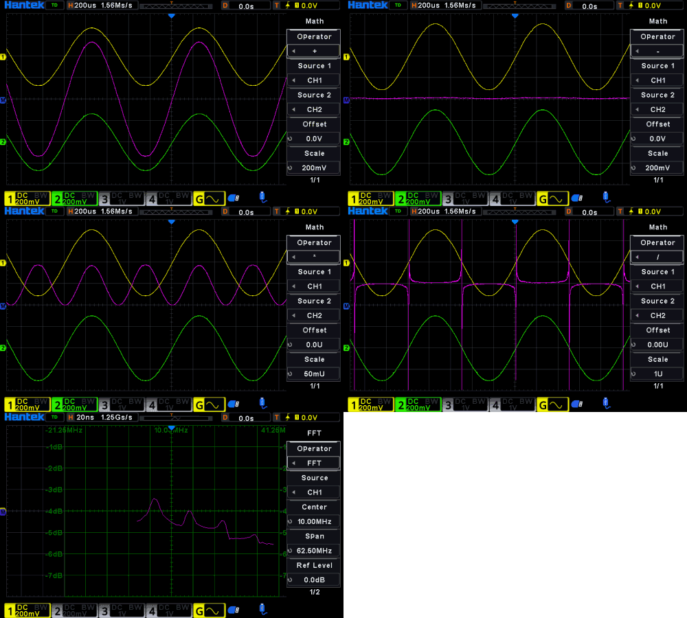
| Operation | A+B, A-B, A*B, A/B, FFT, | |
| Source | CH1-CH4 | |
| FFT | Window Type | Rectangle, Hanning, Hamming, Blackman, Bartlett, Flattop |
| Serial Decoding | ||
| Decoding Type | UART, IIC, SPI, LIN, CAN | |
| UART |
Decode the data of 20 Mb/s UART bus TX/RX signals (5-9 bits), supporting check bit (no parity, odd parity, and even parity) and stop bit (1bit, 1.5bit, 2bit) settings. |
|
| IIC | Decode the address (with or without read/write bits), data, and ACK of the I2C bus. | |
| SPI | Decoding SPI bus data. | |
| LIN | Decode 2. X LIN bus, with a maximum speed of 20Mb/s. | |
| CAN | Decode remote frames, overloaded frames, and data frames from a 5 Mb/s CAN bus. | |
| DVM | ||
| Source | CH1-CH4 | |
| Mode | DC, AC+DC RMS, and AC RMS | |
| Arbitrary Waveform Generator(Opiton) | ||
| Sample Rate | 200MSa/s | |
| Vertical Resolution | 12bit | |
| Max. Frequency | 25MHz | |
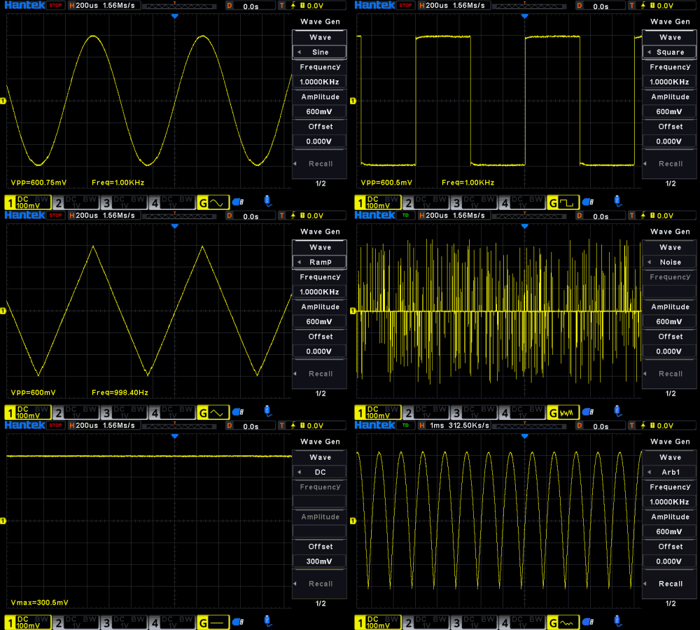
| Standard Waveform | Sine, Square, Ramp, Exp, Noise, DC | |
| Arb Waveform | Arb1-Arb4 | |
| Sine | Frequency Range | 0.1Hz-25MHz |
| Square | Frequency Range | 0.1Hz-10MHz |
| Ramp | Frequency Range | 0.1Hz-1MHz |
| Exp | Frequency Range | 0.1Hz-5MHz |
| Arb | Frequency Range | 0.1Hz-25MHz |
| Waveform Length | 4K | |
| Frequency | Accuracy | 100 ppm (<10 kHz), 50 ppm (>10 kHz) |
| Resolution | 100 mHz or 4 bits (whichever is greater) | |
| Amplitude | Output Range | 10mVpp-7Vpp(HighZ) |
| 5mVpp-3.5Vpp(50Ω) | ||
| DC Offset | Range | ±3.5V, HighZ |
| ±1.75V, 50Ω | ||
| Resolution | 100 uV or 3 bits (whichever is greater) | |
| Accuracy | 2%(1KHz) | |
| Output Impedance | 50Ω±1% | |
| Modulation | AM, FM | |
| AM | Modulating Waveforms: Sine, Square, Triangle | |
| Modulation Frequency: 1Hz-50KHz | ||
| Modulation Depth: 0%-120% | ||
| FM | Modulating Waveforms: Sine, Square, Triangle | |
| Modulation Frequency:1Hz-50KHz | ||
| Modulation Offset:0.1Hz-1KHz | ||
| Burst | N Cycle, Gate | |
| Trigger Source | Internal, Manual | |
| Display | ||
| LCD | 7-inch capacitive multi-touch screen | |
| Resolution | 1024*600 | |
| Persistence | Off, adjustable time afterglow (1s, 5s, 10s, 30s), infinite afterglow | |
| Display Type | vector or point | |
| Waveform Intensity | adjustable | |
| Screen Grid | Dot, Line, and Close | |
| Grid Brightness | adjustable | |
| Screen Brightness | adjustable | |
| I/O | ||
| USB HOST | 1 on the front panel | |
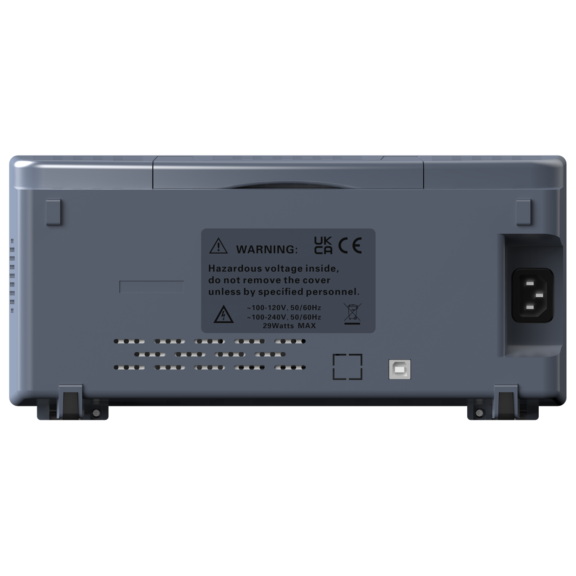
| USB DEVICE | 1 on the rear panel | |
| Power | ||
| Power Voltage | 100-120V, 50/60Hz; 100-240V, 50/60Hz | |
| Power | Max.29W | |
| Fuse | 2 A, 250 V | |
| Environment | ||
| Temperature Range | Operating | 0℃~+50℃ |
| Non-operating | -30℃~+70℃ | |
| Humidity Range | Operating | Below +30℃, ≤90%RH (without condensation) |
| +30℃~+40℃, ≤75%RH (without condensation) | ||
| +40℃~+50℃, ≤45%RH (without condensation) | ||
| Non-operating | Below 65℃, ≤90%RH (without condensation) | |
| Altitude | Operating | Below 3,000 |
| Non-operating | Below 15,000 | |
| Mechanical Characteristics | ||
| Dimensions | 320mm(L)*125mm(W)*152mm(H) | |
| Weight | Package Excluded | ~2.1kg |
| Specifications | ||
| No. of Input Channels |
2 analog channel input/4 analog channel input 1 EXT channel input 1 GEN OUT channel(HRDO800XG series) |
|
| Sampling Mode | Real-time sampling | |
| Max. Sample Rate of Analog Channel |
1.25GSa/s(single-channel) 625MSa/s(dual-channel) 312.5MSa/s(all channels) |
|
| Max. Memory Depth |
125Mpts(single-channel), 50Mpts(dual-channel) 25Mpts(all-channel) |
|
| Peak Detection | Under all the time base settings, capture 1ns glitches | |
| LCD Size and Type | 7-inch display screen | |
| Display Resolution | 1024*600 | |
| Vertical System Analog Channel | ||
| Input Coupling | DC, AC, GND | |
| InputImpedance | 1MΩ ± 1% | |
| Input Capacitance | 17pF±3pF | |
| Maximum Input Voltage | CATⅡ300 VRMS, 400Vpk; Transient overvoltage 1600 Vpk | |
| Vertical Resolution | 12bit | |
| Vertical Sensitivity Range | 500uV/div ~ 10V/div | |
| Offset Range | 500μV/div~20mV/div, ±400mV | |
| 50mV/div~200mV/div, ±2V | ||
| 500mV/div~2V/div, ±40V | ||
| 5V/div~10V/div, ±50V | ||
| Dynamic Range | ±5div (12bit) | |
| Bandwidth Limit | 20MHz; selectable for each channel | |
| DC Gain Accuracy | ± 3% FullScale | |
| DC Offset Accuracy | <200mV/div (±0.1 div±2 mV±1.5%of offset value) | |
| >200mV/div (±0.1 div±2 mV±1.0%of offset value) | ||
| Channel-to-Channel Isolation | 40dB, from DC to maximum rated bandwidth of each model | |
| ESD | ±4kV | |
| Horizontal System--Analog Channel | ||
| Range of Time Base | 500ps/div-1ks/div | |
| Time Base Accuracy | ±50ppm±1ppm/year | |
|
Time Base Delay Range |
before triggering: 8 × SEC/DIV | |
| after triggering: 10 × SEC/DIV | ||
| Time Interval (△T) | Measurement±(1 sample interval)±(2ppm×readout)±50ps | |
| Horizontal Mode | YT:Default | |
| XY:X1=CH1,Y1=CH2,X2=CH3,Y2=CH4 | ||
| SCAN:Time base≥100ms/div,available to enter or exit the SCAN mode by rotating the Horizontal SCALE. | ||
| ROLL:Time base≥100ms/div,available to enter or exit ROLL mode by accessing the menu. | ||
| Acquisition System | ||
| Max. Sample Rate of Analog Channel |
1.25GSa/s(single-channel) 625MSa/s(dual-channel) 312.5MSa/s(all channels) |
|
| Max. Memory Depth |
125Mpts(single-channel), 50Mpts(dual-channel) 25Mpts(all-channel) |
|
| Acquisition Mode | Normal | Default |
| Peak Detection | Capture 1ns glitches | |
| Average Mode | 2, 4, 8, 16…128 are available for you to choose, averaging point by point | |
| High Resolution | 16 bits (max.) | |
| Trigger System | ||
| Trigger Source | Analog channel(CH1-CH4), EXT | |
| Trigger Mode | Auto, Normal, Single | |
| Holdoff Range | 8ns-10s | |
| Trigger Sensitivity | CH1-CH4 | 1 div or 5 mVpp, whichever is larger, <10mV/div |
| 0.5 div, ≥10mV/div | ||
| Trigger Level Range | CH1-CH4 | ± 4 div from the center of the screen |
| EXT | -1.3V-6.5V | |
| Trigger Type | ||
| Trigger Type |
Edge trigger, Pulse trigger, Slope trigger, Overtime trigger, Window trigger, Internal trigger, Under Amp trigger, UART trigger, LIN trigger, CAN trigger, SPI trigger, IIC trigger |
|
| Edge trigger |
Identify triggers by searching for specified edges (rising edge, falling edge, double edge) and voltage levels on the waveform. |
|
| Source channel: CH1~CH4, EXT. | ||
| Pulse trigger |
Set the oscilloscope to trigger on positive or negative pulses of a specified width. You can set the trigger source, polarity (positive, negative), trigger conditions, and pulse width in this menu. |
|
| Source channel: CH1~CH4. | ||
| Slope trigger | Set the oscilloscope to trigger a positive or negative slope from one level to another within a specified time. | |
| Source channel: CH1~CH4. | ||
| Overtime trigger |
Triggered when the time interval (△ T) from the rising edge (or falling edge) of the input signal through the trigger level to the adjacent falling edge (or rising edge) through the trigger level is greater than the set timeout. |
|
| Source channel: CH1~CH4. | ||
| Window trigger |
Window triggering provides high and low triggering levels. When the input signal passes through a high or low trigger level, the oscilloscope triggers. |
|
| Source channel: CH1~CH4. | ||
| Internal trigger |
Triggered when the interval between two consecutive rising (or falling) edges satisfies the set time condition (<,>,!=,=). |
|
| Source channel: CH1~CH4. | ||
| Under Amp trigger | Used to trigger a pulse that crosses one trigger level but does not cross another trigger level. | |
| Source channel: CH1~CH4. | ||
| UART trigger |
Triggering of frame start, frame end, data, checksum errors, and acceptance errors when UART signals are detected. |
|
| Source channel: CH1~CH4. | ||
| LIN trigger | Triggered on the synchronization field of LIN signal, or on specified identifiers, data, or frames. | |
| Source channel: CH1~CH4. | ||
| CAN trigger |
Triggered at the beginning of a CAN signal frame, on a specified type of frame (such as remote frame, data frame, etc.), or on a specified type of error frame. |
|
| Source channel: CH1~CH4. | ||
| SPI trigger | When the timeout condition is met, the oscilloscope triggers when it searches for the specified data. | |
| Source channel: CH1~CH4. | ||
| I2C trigger | Triggered on the start bit, stop bit, no response, address, restart, address, and data of the I2C bus. | |
| Source channel: CH1~CH4. | ||
| Waveform Measurement | ||
| Cursor | Number of Cursors | 2 pairs of XY cursors |
| Manual Mode | Voltage deviation between cursors | |
| Time deviation between cursors | ||
| Reciprocal of dX (1/dX) | ||
| Track Mode | Fix Y-axis to track X-axis waveform point's voltage and time values | |
| Fix X-axis to track Y-axis waveform point's voltage and time values | ||
| XY Mode | Measure the voltage parameters of the corresponding channel waveforms in XY time base mode. | |
| X1=CH1,Y1=CH2,X2=CH3,Y2=CH4 | ||
| Auto Measurement | Number of Measurements | Up to 4 measurements can be displayed at a time. |
| Measurement Source | CH1-CH4 | |
| All Measurement |
Display 32 measurement items for the current measurement channel, with continuously updated measurement results and switchable measurement channels. |
|
| Type |
PKPK, Freq, Average, Vmax, Vmin, Period, Vtop, Vmid, Vbase, Vamp, RMS, OverShoot, PreShoot, PrdRms, PrdAvg, RiseTime, FallTime, +Width, -Width, +Duty, -Duty, FRR, FFF, FOV, FPRE, BWidth, FRF, FFR, LRR, LRF, LFR, LFF |
|
| Statistics | Cur, Avg, Max, Min, Rmse, Count | |
| Waveform Calculation | ||
| Operation | A+B, A-B, A*B, A/B, FFT, | |
| Source | CH1-CH4 | |
| FFT | Window Type | Rectangle, Hanning, Hamming, Blackman, Bartlett, Flattop |
| Serial Decoding | ||
| Decoding Type | UART, IIC, SPI, LIN, CAN | |
| UART |
Decode the data of 20 Mb/s UART bus TX/RX signals (5-9 bits), supporting check bit (no parity, odd parity, and even parity) and stop bit (1bit, 1.5bit, 2bit) settings. |
|
| IIC | Decode the address (with or without read/write bits), data, and ACK of the I2C bus. | |
| SPI | Decoding SPI bus data. | |
| LIN | Decode 2. X LIN bus, with a maximum speed of 20Mb/s. | |
| CAN | Decode remote frames, overloaded frames, and data frames from a 5 Mb/s CAN bus. | |
| DVM | ||
| Source | CH1-CH4 | |
| Mode | DC, AC+DC RMS, and AC RMS | |
| Arbitrary Waveform Generator(Opiton) | ||
| Sample Rate | 200MSa/s | |
| Vertical Resolution | 12bit | |
| Max. Frequency | 25MHz | |
| Standard Waveform | Sine, Square, Ramp, Exp, Noise, DC | |
| Arb Waveform | Arb1-Arb4 | |
| Sine | Frequency Range | 0.1Hz-25MHz |
| Square | Frequency Range | 0.1Hz-10MHz |
| Ramp | Frequency Range | 0.1Hz-1MHz |
| Exp | Frequency Range | 0.1Hz-5MHz |
| Arb | Frequency Range | 0.1Hz-25MHz |
| Waveform Length | 4K | |
| Frequency | Accuracy | 100 ppm (<10 kHz), 50 ppm (>10 kHz) |
| Resolution | 100 mHz or 4 bits (whichever is greater) | |
| Amplitude | Output Range | 10mVpp-7Vpp(HighZ) |
| 5mVpp-3.5Vpp(50Ω) | ||
| DC Offset | Range | ±3.5V, HighZ |
| ±1.75V, 50Ω | ||
| Resolution | 100 uV or 3 bits (whichever is greater) | |
| Accuracy | 2%(1KHz) | |
| Output Impedance | 50Ω±1% | |
| Modulation | AM, FM | |
| AM | Modulating Waveforms: Sine, Square, Triangle | |
| Modulation Frequency: 1Hz-50KHz | ||
| Modulation Depth: 0%-120% | ||
| FM | Modulating Waveforms: Sine, Square, Triangle | |
| Modulation Frequency:1Hz-50KHz | ||
| Modulation Offset:0.1Hz-1KHz | ||
| Burst | N Cycle, Gate | |
| Trigger Source | Internal, Manual | |
| Display | ||
| LCD | 7-inch capacitive multi-touch screen | |
| Resolution | 1024*600 | |
| Persistence | Off, adjustable time afterglow (1s, 5s, 10s, 30s), infinite afterglow | |
| Display Type | vector or point | |
| Waveform Intensity | adjustable | |
| Screen Grid | Dot, Line, and Close | |
| Grid Brightness | adjustable | |
| Screen Brightness | adjustable | |
| I/O | ||
| USB HOST | 1 on the front panel | |
| USB DEVICE | 1 on the rear panel | |
| Power | ||
| Power Voltage | 100-120V, 50/60Hz; 100-240V, 50/60Hz | |
| Power | Max.29W | |
| Fuse | 2 A, 250 V | |
| Environment | ||
| Temperature Range | Operating | 0℃~+50℃ |
| Non-operating | -30℃~+70℃ | |
| Humidity Range | Operating | Below +30℃, ≤90%RH (without condensation) |
| +30℃~+40℃, ≤75%RH (without condensation) | ||
| +40℃~+50℃, ≤45%RH (without condensation) | ||
| Non-operating | Below 65℃, ≤90%RH (without condensation) | |
| Altitude | Operating | Below 3,000 |
| Non-operating | Below 15,000 | |
| Mechanical Characteristics | ||
| Dimensions | 320mm(L)*125mm(W)*152mm(H) | |
| Weight | Package Excluded | ~2.1kg |
| Select | Model | Bandwidth | Channels | Sampling rate | Other |
|---|---|---|---|---|---|
DPO7000 Series
|
500MHz 350MHz 200MHz 100MHz |
4-channels oscilloscope 1-channel waveform generator 16-channels logic analyzer |
2GSa/s single channel 1GSa/s half channel 1GSa/s full channels |
Oscilloscope/16-channels logic analyzer/spectrum analyzer/ arbitrary waveform generator/digital voltmeter/ 6-bit frequency meter and accumulator/protocol analyzer 2G storage depth |
|
DPO8000 Series
|
1GHz 800MHz 500MHz 300MHz |
4-channels oscilloscope 1-channel waveform generator 16-channels logic analyzer |
8GSa/s single channel 8GSa/s half channel 4GSa/s full channels |
Oscilloscope/16-channels logic analyzer/spectrum analyzer/ arbitrary waveform generator/digital voltmeter/ frequency meter and accumulator/protocol analyzer 2G storage depth |
|
HRDO4000 Series
|
3GHz 2.5GHz 2GHz 1GHz 800MHz 500MHz |
4-Channel Oscilloscope 2-Channel Waveform Generator 16-Channel Logic Analyzer |
10GSa/s single channel 10GSa/s half channel 5GSa/s all channel |
4-Channel Oscilloscope/16-Channel Logic Analyzer/Spectrum Analyzer/2-Channel Arbitrary Wave Generator/Digital Voltmeter/6-bit Frequency Meter and Accumulator/Protocol Analyzer/Protocol Generator 2G Memory Depth |
|
HRDO2000 Series
|
500MHz 350MHz 200MHz 100MHz |
4-Channel Oscilloscope 1-Channel Waveform Generator 16-Channel Logic Analyzer |
2.5GSa/s single channel 2.5GSa/s half channel 1.25GSa/s all channel |
4-Channel Oscilloscope/16-Channel Logic Analyzer/Spectrum Analyzer/1-Channel Arbitrary Wave Generator/Digital Voltmeter/6-bit Frequency Meter and Accumulator/Protocol Analyzer/Protocol Generator 2G Memory Depth |
|
DSO2D20(2GSa/s) Series
|
200MHz 350MHz 500MHz |
2CH oscilloscope 1CH waveform generator |
2GSa/s(single channel) 1GSa/s(all channels) |
2CH oscilloscope 1CH waveform generator 5 kinds of serial protocol trigger and decode 32 kinds of auto measurements with statistics |
|
DSO2000 Series
|
150MHz 100MHz |
2 | 1GSa/s | 2 CH oscilloscope 1 CH 25MHz waveform generator 5 kinds of serial protocol trigger and decode 32 kinds of auto measurements with statistics SCPI remote control 2 sets of DVM |
|
DPO6004B(C)/MPO6004D Series
|
80MHz 100MHz 200MHz |
4CH OSC 2CH AFG 16CH LA DVM FFT Serial Bus triggering and decoder |
1GSa/s | 400000 wfm/s 5 serial decoding option 64M memory depth,up to 80,000 segments 13 kinds of waveforms inside 7 inch WVGA capacitive touch screen |
|
DPO6002B(C)/MPO6002D
|
80MHz 100MHz 200MHz |
2CH OSC 2CH AFG 16CH LA DVM FFT Serial Bus triggering and decoder |
1GSa/s | 400000 wfm/s 5 serial decoding option 64M memory depth,up to 80,000 segments 13 kinds of waveforms inside 7 inch WVGA capacitive touch screen |
|
DSO4004C Series
|
80-250MHz | 4CH +1CH WG+ EXT | 1GSa/s | Oscilloscope + waveform generator 7'' High resolution(800x480); 64K memory depth, USB Host/Device, Support U-disk memory, systom update DVM digital DMM, Auto range |
|
DSO4004B Series
|
80-250MHz | 4CH + EXT | 1GSa/s | Oscilloscope 7'' High resolution(800x480); 64K memory depth, USB Host/Device, Support U-disk memory, systom update DVM digital DMM, Auto range |
|
DSO4000C Series
|
200/100/70MHz | 2CH DSO +1CH GENERATOR + External Trigger |
1GSa/s | Oscilloscope+Waveform Generator , 40K Record Length; 7 inch 64K color LCD display (WVGA 800x480), Integrated USB Host/Device |
|
MSO5000D Series
|
200/100/60MHz | 2CH+16CH(LA)+EXT | 1GSa/s(Analog) 500MSa/s(LA) |
7powerful trigger function, 1M Record Length, USB interface system upgrade, 16CH Logic Analyzer, 7'' LCD WVGA 800*480; VGA Optional |
|
DSO5000P Series
|
200/100/70MHz | 2CH + EXT | 1GSa/s | 40K Record Length, USB interface system upgrade, 7'' LCD WVGA 800*480, Powerful trigger function; |
|
DSO5000B Series
|
200/100/60MHz | 2CH+EXT | 1GSa/s | 1M Record Length, USB interface system upgrade, 7'' LCD WVGA 800*480, 7powerful trigger function; VGA Optional |
|
DSO5000BM Series (Discontinued)
|
200/100/60MHz | 2CH+EXT | 1GSa/s | 2M Record Length, USB interface system upgrade, 7'' LCD WVGA 800*480 7powerful trigger function; VGA Optional |
|
DSO5000BMV Series (Discontinued)
|
200/100/60MHz | 2CH+EXT | 1GSa/s | 2M Record Length, Video Help function; Built in 4G SD Card 7'' LCD WVGA 800*480 7powerful trigger function, USB interface system upgrade; VGA Optional |
|
HRDO800 series
|
80MHz 120MHz 250MHz 300MHz |
2/4-channels oscilloscope 1CH waveform generator |
1.25GSa/s 625MSa/s 312.5MSa/s |
2/4CH oscilloscope 1CH waveform generator 5 kinds of serial protocol trigger and decode 32 kinds of auto measurements with statistics |
| Model | Description | View Manual |
| HT300B,HT500B | 350Mhz,500MHz,10:1/1:1 | Download |
| HT-100B,HT-200B | 100MHz,200MHz,10:1/1:1 | Download |
| PP500B | 500MHz,10:1/1:1 | Download |
| PP-80,PP-150,PP-200 | 60MHz,100MHz,200MHz,10:1/1:1 | Download |
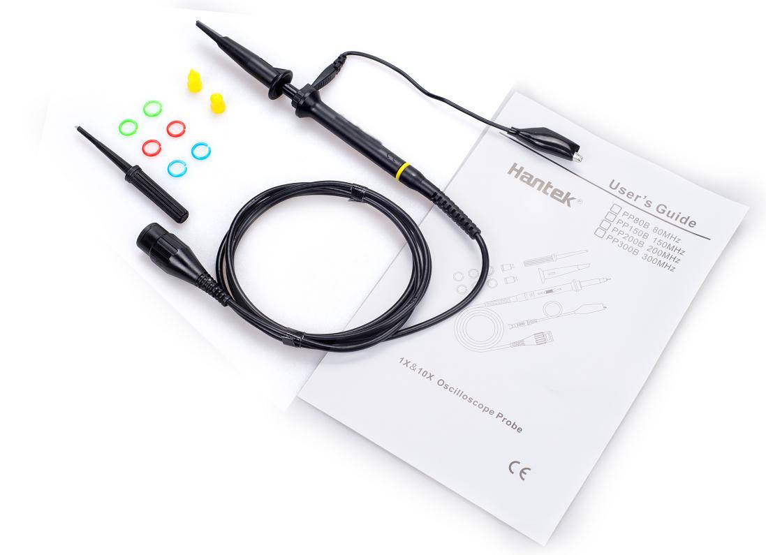
| PP80B, PP150B, PP200B, PP300B | 80Mhz, 150MHz, 200MHz, 300MHz, 10:1/1:1 | Download |
| PP-90 | 80MHz,10:1/1:1 | Download |
| T3100 | 100MHz,100:1,2000VDC Peak AC | Download |
| Model | Description | View Manual |
| CC65 | AC/DC: 0 – 20KHz,20mA to 65A DC | Download |
| CC650 | AC:0 – 5KHz,1A - 500A ,DC:1A - 650A | Download |
| CC800 | AC:0 – 5KHz,1A - 500A ,DC:1A - 800A | Download |